NTSB Releases Images Of Fatigue Cracks In Chalk's Wreckage | Aero-News Network
Aero-News Network
RSS icon RSS feed
podcast icon MP3 podcast
Subscribe Aero-News e-mail Newsletter Subscribe

Airborne Unlimited -- Most Recent Daily Episodes

Episode Date

Airborne-Monday

Airborne-Tuesday

Airborne-Wednesday Airborne-Thursday

Airborne-Friday

Airborne On YouTube

Airborne-Unlimited-05.06.24

Airborne-NextGen-04.30.24

Airborne-Unlimited-05.01.24 Airborne-AffordableFlyers--05.02.24

Airborne-Unlimited-05.03.24

Thu, Dec 22, 2005

NTSB Releases Images Of Fatigue Cracks In Chalk's Wreckage

Accident Claimed 20 Lives

(Editor's Note: The following is the unedited text of the National Transportation Safety Board's latest release concerning the December 19 accident involving a Chalk's Ocean Airways Grumman seaplane. While the probable cause of the accident has yet to be released, it appears increasingly likely fatigue cracks in the aircraft's main spar caused the right wing to separate from the aircraft, sending the plane into the waters of Miami's Government Cut shortly after takeoff.)

The National Transportation Safety Board has released photos depicting fatigue cracks found on the separated wing of the Chalk’s Ocean Airways plane that crashed into the water near Miami Beach on Monday.

On Tuesday afternoon, the right wing of the aircraft was recovered. The wing had separated at the inboard section, at the wing/fuselage juncture. Safety Board engineers and metallurgists agree that the signatures are consistent with fatigue fractures. Portions of the wing are at the NTSB metallurgy laboratory in Washington, DC.

As part of the investigation of this accident, which claimed 20 lives, the Safety Board will extensively examine the wing and other structures in the coming days. The probable cause of this accident has not been determined.

IMAGE 1: Overall view of the inboard end of the right wing as it was recovered from the water. An unlabeled arrow indicates the lower spar cap of the rear spar where fatigue features were observed.

IMAGE 2: Closer view of the fracture surface at the inboard end of the lower spar cap of the right wing rear spar. Unlabeled arrows indicate the location of two offset drilled holes.

IMAGE 3: Closer view of the fatigue region in the horizontal leg of the lower spar cap of the rear spar. Unlabeled brackets indicate fatigue origin areas at the surfaces of the fastener hole, and dashed lines indicate the extent of the fatigue region visible on the fracture surface.

FMI: www.ntsb.gov

Advertisement

More News

ANN's Daily Aero-Term (05.09.24): Hold Procedure

Hold Procedure A predetermined maneuver which keeps aircraft within a specified airspace while awaiting further clearance from air traffic control. Also used during ground operatio>[...]

ANN's Daily Aero-Term (05.06.24): Altitude Readout

Altitude Readout An aircraft’s altitude, transmitted via the Mode C transponder feature, that is visually displayed in 100-foot increments on a radar scope having readout cap>[...]

ANN's Daily Aero-Linx (05.06.24)

Aero Linx: European Hang Gliding and Paragliding Union (EHPU) The general aim of the EHPU is to promote and protect hang gliding and paragliding in Europe. In order to achieve this>[...]

Airborne-NextGen 05.07.24: AI-Piloted F-16, AgEagle, 1st 2 WorldView Sats

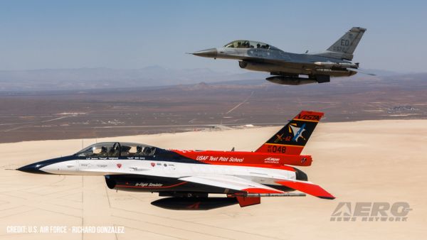
Also: Skydio Chief, Uncle Sam Sues, Dash 7 magniX, OR UAS Accelerator US Secretary of the Air Force Frank Kendall was given a turn around the patch in the 'X-62A Variable In-flight>[...]

Aero-News: Quote of the Day (05.07.24)

"The need for innovation at speed and scale is greater than ever. The X-62A VISTA is a crucial platform in our efforts to develop, test and integrate AI, as well as to establish AI>[...]

blog comments powered by Disqus


Advertisement

Advertisement

Podcasts

Advertisement

© 2007 - 2024 Web Development & Design by Pauli Systems, LC