Setting Engine Technology Back 100 Years Isn't Easy
 John Nowicki, who in his "real job" is in charge
of business development for the Aerospace portion of Packer
Engineering, met the Wright Redux folks at an EAA chapter meeting.
They talked about their plans to build a Wright Flyer, to
commemorate the hundredth anniversary of controlled powered flight.
Nowicki was impressed, and took the idea to Dr. Ken Packer (a
former Marine Corsair pilot), who enthusiastically committed to
lead the engineering/building project of the Redux engine.
John Nowicki, who in his "real job" is in charge
of business development for the Aerospace portion of Packer
Engineering, met the Wright Redux folks at an EAA chapter meeting.
They talked about their plans to build a Wright Flyer, to
commemorate the hundredth anniversary of controlled powered flight.
Nowicki was impressed, and took the idea to Dr. Ken Packer (a
former Marine Corsair pilot), who enthusiastically committed to
lead the engineering/building project of the Redux engine.
The Drawings Don't Tell All
 The Smithsonian's Wright engine drawings are
believed to be as close to the Wright engines as possible; but
they're not perfect, nor are they complete. They even contain at
least one impossible contradiction. Even so, there's plenty of
information there, Nowicki believes, to make as close a replica as
humanly possible, given some judgment, some knowledge of history,
insight into steam-engine technology; and turn-of-the-century
metallurgy and engine design. The Wright Redux engine itself is
completely built, as the drawings depict, from the Smithsonian.
John Nowicki noted that the Smithsonian drawings don't contain all
the materials, tolerances, and so on, that would be found on modern
engineering drawings. He did note, "The Smithsonian basically
back-engineered what were believed to have been... the original.
We're as 'replica' as you can get."
The Smithsonian's Wright engine drawings are
believed to be as close to the Wright engines as possible; but
they're not perfect, nor are they complete. They even contain at
least one impossible contradiction. Even so, there's plenty of
information there, Nowicki believes, to make as close a replica as
humanly possible, given some judgment, some knowledge of history,
insight into steam-engine technology; and turn-of-the-century
metallurgy and engine design. The Wright Redux engine itself is
completely built, as the drawings depict, from the Smithsonian.
John Nowicki noted that the Smithsonian drawings don't contain all
the materials, tolerances, and so on, that would be found on modern
engineering drawings. He did note, "The Smithsonian basically
back-engineered what were believed to have been... the original.
We're as 'replica' as you can get."
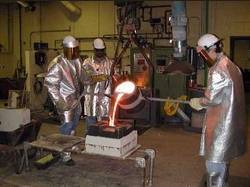
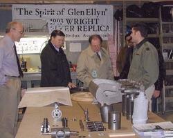
It's a big group of volunteers, that makes this possible.
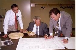 "We have 30 companies that have contributed their
efforts toward this project," Mr. Nowicki (at right of photo, with
Dr. Packer, seated, and casting engineer Joe
Santner) said. "We took the Smithsonian drawings of the engine
block, and Packer Technologies Inc (PTI) turned them into a CAD
model; the Terry Austin Group in Quincy (IL) made patterns
utilizing the lost foam method. Then in Cincinnati, we got
the Willard Industries folks to actually pour the castings."
"We have 30 companies that have contributed their
efforts toward this project," Mr. Nowicki (at right of photo, with
Dr. Packer, seated, and casting engineer Joe
Santner) said. "We took the Smithsonian drawings of the engine
block, and Packer Technologies Inc (PTI) turned them into a CAD
model; the Terry Austin Group in Quincy (IL) made patterns
utilizing the lost foam method. Then in Cincinnati, we got
the Willard Industries folks to actually pour the castings."
Putting this together had its 'easy' parts, as well as its
'hard' ones: "So many have wanted to be part of this project," he
told us, "nobody has charged for anything." It wasn't all 'easy,'
though. "Keep in mind, we're asking for 'two of everything.'"
They're building enough parts to build two engines. "One set is for
spares, Nowicki explained. "If everything goes as planned, the
spares will be built into a separate engine, for display."
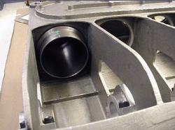
 As Mr. Nowicki told ANN, "It is truly a 'replica
engine.' All the cast parts were sand cast, the pistons and
cylinders, combustion chambers, valve guides and seats, valve heads
and the flywheel. One set of cylinders, however, were cut from
solid cast iron, not steel." The Smithsonian drawings did note some
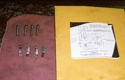
near-detail: "The fasteners are pretty-much called out:
'fillister-head screws,' 'brass screws,' 'round-head screws;' we're
using non-graded hardware, similar to what they would have had back
then."
As Mr. Nowicki told ANN, "It is truly a 'replica
engine.' All the cast parts were sand cast, the pistons and
cylinders, combustion chambers, valve guides and seats, valve heads
and the flywheel. One set of cylinders, however, were cut from
solid cast iron, not steel." The Smithsonian drawings did note some
near-detail: "The fasteners are pretty-much called out:
'fillister-head screws,' 'brass screws,' 'round-head screws;' we're
using non-graded hardware, similar to what they would have had back
then."
There are very few deviations from the Wright model. "We used
more modern alloy of aluminum, a 356 aluminum for the block
[the alloy the Wrights used couldn't have been welded, for
instance]; but everything else is just as they built it."
Sounds modern; sounds stone-age. All of it is clever.
Mr. Nowicki continued, "It's an aluminum block, with cast-iron
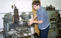
cylinders. Charles Taylor, who made the actual engine the Wrights
flew, made the original with nothing but a lathe, a drill press,
and hand tools. All he had were the drawings he and the Wrights
made; and he had seen a similar [internal combustion] engine,
before." Taylor, fortunately, had a lot of external-combustion
experience. "A lot of it looks like steam-engine technology," John
told us, approvingly.
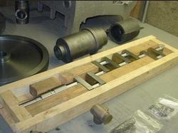 "The crankshaft is a work of art," the Packer man
told us. "It was made out of a 1 5/8" x 8" by 36" 4340 steel plate
(a material quite similar to what the Wrights used), that weighed
140 pounds. The finished crank weighs just 22 pounds. It was
machined out by one of our people, who did crankshafts for the rail
industry. Then it was ground in St. Charles (IL), by Auto Machine,
who usually grind for classic and vintage autos." It's a five-main,
four cylinder crank, "but it's quite flimsy. If you put it between
centers, you can push on it and move it .010 to .015"; but when
it's in its bearings," he assured us, "it's sturdy."
"The crankshaft is a work of art," the Packer man
told us. "It was made out of a 1 5/8" x 8" by 36" 4340 steel plate
(a material quite similar to what the Wrights used), that weighed
140 pounds. The finished crank weighs just 22 pounds. It was
machined out by one of our people, who did crankshafts for the rail
industry. Then it was ground in St. Charles (IL), by Auto Machine,
who usually grind for classic and vintage autos." It's a five-main,
four cylinder crank, "but it's quite flimsy. If you put it between
centers, you can push on it and move it .010 to .015"; but when
it's in its bearings," he assured us, "it's sturdy."
Harley Davidson used a tin can for a carburetor. The Wrights
didn't.
 There is no 'carburetor' at all, per se.
John explained how the intake side of the engine works: "The
induction system is just a small cup that sits on the engine
itself. The fuel goes into a tray that sits on the block; heat from
the block vaporizes the fuel in the tray, and that gets sucked into
the intake valves, which are vacuum-operated." (The exhaust valves
are cam-actuated.) The valves are clever, too: cast-iron, with mild
steel stems.
There is no 'carburetor' at all, per se.
John explained how the intake side of the engine works: "The
induction system is just a small cup that sits on the engine
itself. The fuel goes into a tray that sits on the block; heat from
the block vaporizes the fuel in the tray, and that gets sucked into
the intake valves, which are vacuum-operated." (The exhaust valves
are cam-actuated.) The valves are clever, too: cast-iron, with mild
steel stems.
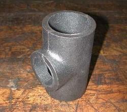
 "The ignition system," he continued, "is bizarre.
There's no spark plugs; there's a set of cam-operated 'points'
(right) in each combustion chamber (photo above). When they open
and close, the spark [from a magneto, actually more of a generator,
then made by Dayton Electric Company, which is now known as Delco
--ed.] would touch off the mixture. We've built a magneto, out of
cast iron and cast brass, with an armature made by Bison
Engineering (St. Charles, IL)."
"The ignition system," he continued, "is bizarre.
There's no spark plugs; there's a set of cam-operated 'points'
(right) in each combustion chamber (photo above). When they open
and close, the spark [from a magneto, actually more of a generator,
then made by Dayton Electric Company, which is now known as Delco
--ed.] would touch off the mixture. We've built a magneto, out of
cast iron and cast brass, with an armature made by Bison
Engineering (St. Charles, IL)."
Volunteers!
 John marveled out loud how so much could have been
done at all; he wanted us to realize how much the volunteers --
and, on this project, they're all volunteers -- have done. "We call
this 'Midwest Volunteerism at its finest.' Add to the list I
already started: Research Automation (Aurora IL), who, with
Advantage Machine, finished one of the block castings; another
block was machined by Craftsman Tool & Mold (also of Aurora).
All the steel and rounds came from Napco Steel, out of West
Chicago."
John marveled out loud how so much could have been
done at all; he wanted us to realize how much the volunteers --
and, on this project, they're all volunteers -- have done. "We call
this 'Midwest Volunteerism at its finest.' Add to the list I
already started: Research Automation (Aurora IL), who, with
Advantage Machine, finished one of the block castings; another
block was machined by Craftsman Tool & Mold (also of Aurora).
All the steel and rounds came from Napco Steel, out of West
Chicago."
John noted, "A lot of the machining work here was done by
high school and college-age kids. They helped develop the
metallurgy; they poured the cast iron; they made some of the
smaller aluminum parts." The American Foundry Society (in Des
Plaines, IL) did the pistons, some of the cylinders, the combustion
chambers, the cast-iron flywheel, and a lot of the other parts.
Specs, please.
 The 201 cubic inch engine is expected to make 16
horsepower at 1600 rpm. Overall weight will be between 150 and 160
pounds. It's a little lighter than the Wright's piece. There was a
little extra machining of the cast-iron cylinders, to improve
cooling and lighten the overall weight: "We took off 1/8" from the
OD (inside the water jacket) on the cylinders, which makes them 3
lbs lighter, each," John explained.
The 201 cubic inch engine is expected to make 16
horsepower at 1600 rpm. Overall weight will be between 150 and 160
pounds. It's a little lighter than the Wright's piece. There was a
little extra machining of the cast-iron cylinders, to improve
cooling and lighten the overall weight: "We took off 1/8" from the
OD (inside the water jacket) on the cylinders, which makes them 3
lbs lighter, each," John explained.
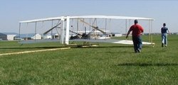
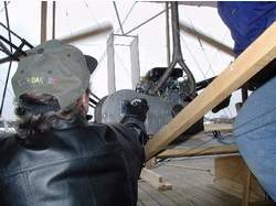
The weight of the Wright replica engine is, though, considerably
higher than the 'mule' engine that's been used for the first
flights of the Wright Redux airframe. The engine that was flown is
a modern V-twin four-stroke, making 20 hp (below, on thrust-test
day). It's geared to turn the props at the proper rpm. [Because
it's lighter than the replica Wright engine, it has had weight
added in the engine mount, so the whole package duplicates the
weight and CG of the real Wright engine --ed.]
 The compression ratio is about 4.4:1, on a 4-inch
bore. Stroke is in the neighborhood of 4". Connecting rod length is
about 10".
The compression ratio is about 4.4:1, on a 4-inch
bore. Stroke is in the neighborhood of 4". Connecting rod length is
about 10".
Everything shows ingenuity. Nowicki told us, "The rod is made up
of five parts: crank and piston ends are cast bronze; there's a
small connector that screws into that, and gets brazed into a piece
of steel tubing."
"The wristpin is solid with the piston; it floats on the rod,"
John noted. The drawings here are clearly in conflict -- there were
more than one engine on the drawings. [The drawings, for
instance, show both the rod/pin and piston/pin matings as
solidly-mounted. Obviously, that cannot work, in a single engine
--ed.]
The pistons have three cast-iron compression rings, like a steam
engine. There's .004" piston-to-wall clearance. Main bearings are
poured, split-shell babbitt. The halves will be 'scraped' in. Rod
bearing clearance will be about .0015 to .002"
The water system holds a gallon and a half to two gallons.
"There's a sort of a standpipe system," Mr. Nowicki said. "Cold
water comes in through the top of the engine. The hot water goes
into a secondary compartment, forcing circulation. Steam pressure
and hot water rise, and spill back into the colder water in the
system." It's basically a thermo-siphon system, like on a Model T
Ford.
Gas and oil:
 The Wright Flyer held just short of half a gallon
-- they weren't going fly the Atlantic with it. For the replica's
flight, even the gasoline is special. "Exxon-Mobil even formulated
'period fuel' for us. It's about 48-octane," our guide said, and
went to the next logical question, before we
The Wright Flyer held just short of half a gallon
-- they weren't going fly the Atlantic with it. For the replica's
flight, even the gasoline is special. "Exxon-Mobil even formulated
'period fuel' for us. It's about 48-octane," our guide said, and
went to the next logical question, before we
asked. "We're using modern oil." That's because the Wright's first
engine had, "no lubrication system -- just open the side panels,
and squirt it in and let it go: no splash, no sump, no nothing.
[Later 1903-model Wright engines, and all subsequent Wright
engines, had oiling systems.] We're going to have holes in the
bearing caps, like the Wrights had." He is making one other
concession to engine life: "We're using Lubriplate 180 as an
assembly lube."
Sometimes there are safety concessions that need to be made. The
Wright's engine avoided one obvious one, which Packer considers
important. "There's no throttle; we're adding a safety mag ground;
but the real way to shut the engine down was to shut off the fuel."
That fuel shutoff is also employed on the Redux machine.
How do you break in an engine with a 5-hour TBO?
Very carefully, John said. "We probably won't run more than
about 5 to ten hours, ten minutes at a time. We'll run four or five
test sessions, and then put it on the airplane... The engine should
get its first test run in the next couple weeks."
One other parallel...
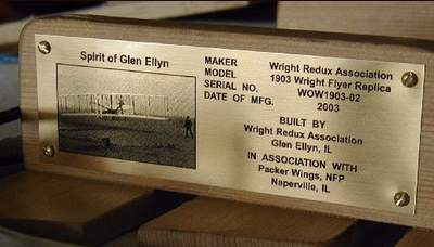
There's yet another parallel between the Wright Redux and the
Wrights' tradition. When this airplane goes into the Museum of
Science and Industry in Chicago, it will be accompanied by a plaque
that will commemorate the builders. Octave Chanute, who helped the
Wright Brothers, also helped found the Western Society of
Engineers... which is donating the Wright Redux plaque for the
Museum of Science and Industry exhibit.
 ANN's Daily Aero-Linx (04.13.24)